TANGLEWOOD Release Date Announced

TANGLEWOOD will be released on 14th August 2018 on SEGA Mega Drive (obviously…), Windows, Mac, and Linux!

It’s finally happening!

Oh, we have a trailer, too!

And some soundtrack!

And a Steam page!

https://store.steampowered.com/app/837190/TANGLEWOOD/

It’s all very exciting and terrifying! Thank you to EVERYONE who has followed this journey so far. It’s been so weird looking back through the earliest posts on this blog, back to when I was struggling to add two numbers together! It’s been a wild ride.


Matt ❤

TANGLEWOOD Tech Demo 0.1.04 Released

A fresh demo of Tanglewood has been released, showing off some big changes, brought to you by our newly formed, Kickstarter funded team!

Click to reserve your Tanglewood cartridge for SEGA Mega Drive

Tech Demo 0.1.04 marks a significant milestone in Tanglewood’s development. We’ve now completed considerable work upgrading the engine, editor and toolchain which will boost our productivity and enable us to realise some big features on our wishlist. We’ve used the updated tools to re-implement most of the existing work to a far higher standard than the original demo, and we hope it shows!

The demo is still only a small slice of what’s to come. It shows off one of the nine environments in Tanglewood, and only one of the six enemy types we have planned. We have a big bag of mechanics and tricks and puzzles ready to roll out for the other levels, and hopefully we’ll be able to show some of those off soon!

Download the demo ROM here: http://www.mediafire.com/file/as5beiw709o141f/TANGLEWD.BIN

The ROM has been tested with all major emulators, but naturally, we recommend you play on a genuine SEGA console 😉

Megafounder Continued Funding

We’ll be using our new demo release to drive a promotional campaign to see the end of the Megafounder funding stage off with a bang, and hopefully reach that last stretch goal for the SEGA Dreamcast HD conversion!

We’ll be running the continued crowdfunding for around 4 weeks following this release, before we close it down and start counting the materials needed for manufacture.

As usual, please lend us a hand spreading details of our continued campaign, by sharing this link around: https://www.megafounder.com/tanglewood

Matt

Tanglewood Tech Demo 0.0.11

I’m pleased to announce the very first tech demo release of Tanglewood!

The demo represents the first milestone in Tanglwood’s development. It is a proof of the engine, editor, toolchain and content pipeline, the basic mechanics of the game, controls and platforming behaviour, the art and animation styles, and some early puzzles.

These two levels have been a sandbox for mechanics and puzzle testing since development of the game began, and with a little work they’ve been turned into functional showcases for Tanglewood’s early progress.

tech_demo_titles

tech_demo_screen1

This is a prototype of a game in its very early stages of development. Some assets are placeholder, and all tech is a work in progress. The look, feel, quality and feature set may not be representative of the final product.

The tech demo contains tests of the following features:

– Nymn: basic movement and platforming, sleep/wake up behaviour, running, walking, jumping, pushing (animation missing), rolling, gliding, death
– Fuzzls: all alert states, physics, and rolling behaviour
– Djakk monsters: initial encounter logic, A.I. behaviour tree, tracking, attacking, search patterns
– Colour abilities: yellow (glide) and green (time slow/cloak)
– Flues: varying output velocities and hold durations, multiple occupants, linked flues
– Boulders: physics, rolling behaviour, cracking and respawning
– Director Cam cutscenes
– Time of day system
– Static blockades

tech_demo_screen2

tech_demo_screen3

It’s an early tech demo/prototype, so expect to see these problems and more:

– Missing fall animation
– Missing push animation
– Framerate drop during Djakk monster encounter in Level 1
– It’s possible to get Fuzzls stuck against walls if they’re rolling fast enough to jump over flues
– It’s possible to get the Fuzzls in Level 2 stuck by rolling them back to the flue at the start
– The Djakk in Level 2 can reach the flue on the right-hand side if left alone in search state for a long time
– It’s possible to get Nymn to sleep in mid-air by jumping at the end of a level
– It’s possible to push the boulder in Level 2 whilst using time-slow ability (boulder won’t animate)
– Footstep sound effects take priority over others, which may result in some SFX cutting out whilst running (ambience, Fuzzl SFX)
– Many known sprite/background draw priority glitches, and tile flipping errors
– Dead Djakks use the older placeholder palette (yellow feet/teeth)
– Occasionally the wrong instruments are chosen for an SFX (emulator only)
– Double-tapping C with the cloak ability will choose the wrong palette

tech_demo_screen4

tech_demo_screen5

Download link over at the Tanglewood forum

Tanglewood: Introducing Djakk Monsters

Introducing Djakk Monsters

There’s a reason our friend Nymn is so keen to get back home before dark. That reason is a huge, snarling, fearsome beast that emerges from its cave at night, with the blood of its last victim still dripping from its teeth, and an insatiable appetite for Nymn’s face.

djakk_0
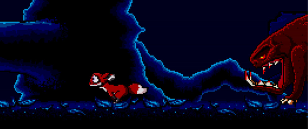
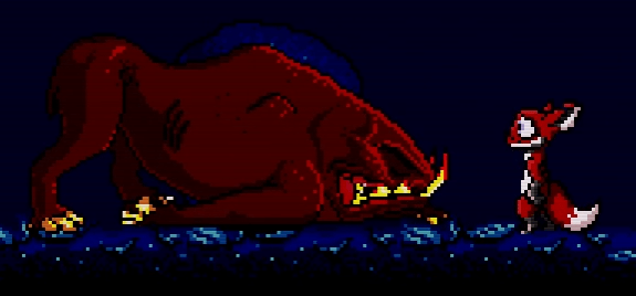
Djakk monsters have been a threat to Tanglewood for as long as its inhabitants can remember. The lore speaks of an ancient tribe of hunters who saddled them up and rode them right to the edge of the forest, hunting the Djunn kind for as far as they could smell. Long gone are the bad rulers of the lands, but their big ugly pets remained.

A Djakk fight is a long and drawn out challenge, they are expert trackers and will chase Nymn to the ends of the Earth for a taste of his innards. As the player you must be quick, be forever wary of the Djakk’s presence (however much you think you’ve lost it underneath you), and never underestimate their ability to break through obstacles or foil your traps. They’ve seen it all before.

Getting rid of a Djakk will need to be done in different ways for each encounter. In the demo I’ve been working on, a precariously placed boulder is primed ready to drop on the unsuspecting beast’s head, but that’s just a set-up scenario to show off the mechanics quickly. The monster will roar on sight, then immediately give chase, but if he loses you he will wander over to the last place Nymn was spotted to sniff out your tracks. This can be used very much to your advantage, as a way to coax a Djakk into standing on a particular spot – as long as you’re cunning in your escape.

djakk_3

I have plans for some of the Djakk encounters to last entire levels, and maybe more. They provide an interesting narrative reason for keeping the forest floor out of bounds until the creature has been defeated. Flues, Fuzzls, and all other tricks and traps inhabiting the surface would be unusable, making whole sections of the game, pickups and secrets inaccessible unless Nymn figures out a way to dispose of his unwelcome companion. More importantly, Nymn is looking for somewhere to sleep to wait out the rest of the night terrors, and with this thing around it’s unlikely there will be anywhere safe to rest.

djakk_4

The Djakk posed quite an early technical challenge for the game engine; it’s the largest sprite sheet in the game so far, which is costly both in subsprite count and bandwidth to transfer animation frames. Many of the routines featured in my Mega Drive coding tutorials for sprite management were too slow and naïve in implementation, and it’s taken me quite a while to rewrite them to cope with these huge creatures. The work has certainly paid off, I’m quite proud of our Djakk so far.

Future plans for the Djakk include the ability to traverse the terrain, perhaps being able to leap across a crevasse or run up a ramp to reach higher. There’s also the possibility of weak tree branches, both as an added threat to Nynm and an advantageous point to coax a Djakk onto, to see it fall to its death. For the moment we’ll be keeping it simple, this huge sprite sheet is tricky for our artist to maintain, so we’ll squeeze what we can out of the animations available first.

See the ugly fellow in action in this short demo video:

Matt

Sega Megadrive – 10: Sound Part I – The PSG Chip

Okay, despite my promises of regular updates I’ve fallen a little behind, and you can thank a short holiday, music festivals, my Real Job™, and many many videogames for that.

Welcome to the first article in the Sound series! Being a full-time audio engine programmer, game audio is a subject very close to me, so this should get quite tasty. One of the most nostalgic and fondly remembered parts of my childhood were the soundtracks accompanying my favourite games, many of which I still find technically impressive, especially considering the machine’s audio capabilities didn’t really weigh up to those of its competing consoles, requiring the sound designers to squeeze so much out of so little.

There are three chips which can create, or are involved in the creation of sound in the Megadrive:

The PSG chip

The Programmable Sound Generator, the same Texas Instruments SN76489 chip used in the Sega Master System. It’s a simple device, comprising 4 mono channels – 3 channels generate a square wave at varying frequencies, and the 4th is a white noise generator. Each channel can have its attenuation modified, and the frequency of the wave or density of the white noise.

It’s got a good trick up its sleeve – you can set the wave generators to stick at +ve, then switch the attenuation registers high and low very quickly to make it behave like a 1-bit DAC, meaning it’s capable of playing PCM data. It won’t win any sound quality awards, and with the available memory I doubt it could stream entire soundtracks, but it can pull of some short voice overs and sound effects which can’t be synthesised.

The FM chip

The Yamaha YM2612 – a stereo, 6 channel sound chip with lots to brag about. 6 FM voices with 4 operators each, Yamaha synthesizer patch compatibility, envelopes, a distortion oscillator, two built-in timers, and a DAC for playing 8-bit PCM data.

Each ‘operator’ of a channel has an input and output (from and to other operators, or the final output), a frequency and an envelope. These operators can be routed in various formations to create algorithms suited for different instrument types (harp, strings, flute, brass, xylophone, piano, organ, guitar and various percussion). It’s quite a complex beast and requires some serious effort to get anything other than basic beeps out of it, but I’ve found plenty of documentation and examples so hopefully I can get it singing.

The Z80 chip

The 8-bit Zilog Z80, which was the Sega Master System’s main CPU, made its way to the Genesis both for backwards compatibility and as a slave CPU to the 68000. Neither of the sound chips can be programmed and left to get on with it, they need their hands holding for the whole session, having data fed to them constantly. This would be quite a pain to manage on the 68k, and it would be impossible to keep up a feed of PCM data whilst trying to process an entire game at the same time, so the Z80 can be used as a secondary CPU for managing the audio. Unfortunately, it doesn’t have any knowledge of the sound chips or how to operate them by default – we need to write our own sound driver (a sequencer, and a program to feed PCM data) in Z80 assembler, generate a binary and load it on startup. This means learning another assembly language, but I’m certainly up for the challenge.

Programming the PSG

I won’t jump straight in the deep end and write a Z80 audio driver just yet, I need to get a handle on the basics. This article covers the simplest case – operating the PSG from the 68000.

The PSG has 4 channels3 square wave generators and 1 white noise generator. I’ll concentrate on just the wave generators to begin with. Each channel is controlled by 2 registers: one for the attenuation, and one for the wave generator’s counter reset. The attenuation registers are 4 bits in size, allowing 16 possible volume values, from 0x0 (no attenuation; full volume) to 0xF (full attenuation; no volume). The counter reset registers are 10 bits in size, and store the square wave’s time until the polarity of the output is flipped in clock ticks / 16 (essentially the “wave width / 2”).

So, assuming an NTSC setup with a clock frequency of 3579545 Hz, a register value of 0xFE would generate a square wave at a  frequency of 440.4 Hz (3579545  ÷ (2 x 16 x reg value)).

To program the PSG, we write to its control port at 0x00C00011, one byte at a time. The most significant bit is the latch, telling the chip that this is the first or only byte it’s expected to receive. Bits 6-5 mark the channel ID (0 – 3) that we’re about to modify. Bit 4 indicates that we’re writing either the attenuation value or wave/noise settings. That leaves 4 bits for the data, which may or may not be enough. If there wasn’t enough space, we send a second byte with the latch bit OFF, indicating it contains the remaining data and is not a new command, with the upper 6 bits of data in bits 5-0.

So, a quick recap:

First byte:
Bit 7    : Latch. ON indicates this is the first (or only) byte being written
Bits 6-5 : Channel ID (0-3)
Bit 4    : Data type. ON if data bits contain attenuation value, OFF if they contain the square wave counter reset
Bits 3-0 : The data. Either all 4 bits of the attenuation value, or the lower 4 bits of counter reset value

Second byte:
Bit 7    : Latch. OFF indicates this is the second byte, and will only contain the remainder of data
Bit 6    : Unused
Bits 5-0 : Upper 6 bits of data

So, let’s make channel 0 produce 440.4hz. The first byte needs the latch ON (to indicate it’s the first byte), the channel ID, the data type bit OFF (to indicate we’re writing a counter reset value), and the lower 4 bits of the value 254. The second byte needs the latch OFF (it’s the second byte), and the upper 6 bits of the value 254.

They’re written to the PSG control port at address 0x00C00011:

move.b #%10001110, 0x00C00011 ; Latch ON, channel 0, counter data type, lower 4 bits of data
move.b #%00001111, 0x00C00011 ; Latch OFF, upper 6 bits of data

The channel will have been initialised fully attenuated, so we need to turn the volume up to hear anything. The attenuation is specified in 4 bits, where 0 is fully attenuated and 16 is full volume, so we can fit the command and data in a single byte. Latch needs to be ON, channel ID is 0, data type bit ON to indicate attenuation data, followed by the 4-bit value:

move.b #%10010000, 0x00C00011 ; Latch OFF, channel 0, attenuation data type, 4 bits of data

Immediately after writing, the PSG will emit a constant tone of 440.4hz, at full volume.

A poor man’s sequencer

Even with just one feature of the PSG covered, it’s enough to make a basic tune. By defining an array of counter reset values, with sustain times, we can iterate over them and play the notes. Here’s some example data – it’s one crudely written line from Scott Joplin’s The Entertainer. Each “note” is 32 bits in size, the first word is the sustain time in vsync frames, and the second word is the counter reset value:

 chan0_notes:
   dc.w 0x0010, 0x02f8, 0x0010, 0x02cd, 0x0010, 0x02a5, 0x0010, 0x01aa, 0x0008, 0x0000 ; D3 D#3 E3 C4 .
   dc.w 0x0010, 0x02a5, 0x0010, 0x01aa, 0x0008, 0x0000 ; E3 C4 .
   dc.w 0x0010, 0x02a5, 0x0010, 0x01aa, 0x0010, 0x0000 ; E3 C4 .
   dc.w 0x0010, 0x01aa, 0x0010, 0x0193, 0x0010, 0x017c, 0x0010, 0x0152, 0x0010, 0x01aa, 0x0010, 0x017c, 0x0010, 0x0152, 0x0008, 0x0000 ; C4 C#4 D4 E4 C4 D4 E4 .
   dc.w 0x0010, 0x01c4, 0x0010, 0x017c, 0x0008, 0x0000 ; B3 D4 .
   dc.w 0x0010, 0x01aa ; C4
 chan0_notes_end
 chan0_notes_len equ chan0_notes_end-chan0_notes
 chan0_notes_count equ chan0_notes_len/4

In order to play it, we loop over the notes, apply the counter reset value to channel 0, and wait for the defined amount of frames. It’s pretty simple:

 move.b #%10010000, psg_control ; Channel 0 full volume

 lea chan0_notes, a0            ; Notes to a0
 move.l #chan0_notes_count, d1  ; Number of notes to d1
 subi.l #0x1, d1                ; -1 for counter

 @NextNote:

 move.w (a0)+, d0       ; Delay to d0 and inc. pointer
 move.w (a0)+, d2       ; Counter reset to d2 and inc. pointer
 move.b d2, d3          ; Lower byte of counter reset to d3
 and.b #%00001111, d3   ; Clear top nybble (leave lower 4 bits)
 or.b #%10000000, d3    ; Latch bit (7) on, chan 0 (6-5), tone data bit (4) off
 move.b d3, psg_control ; Write to PSG port

 move.w d2, d3          ; Counter reset to d3 again
 ror.w #0x4, d3         ; Shift right 4 bits
 and.b #%00111111, d3   ; Only need bits 5-0 (upper 6 bits of the 10 bit value)
 move.b d3, psg_control ; Write to PSG port

 move.l d1, -(sp)       ; Backup d1
 jsr WaitFrames         ; Delay frames is in d0
 move.l (sp)+, d1       ; Restore d1

 dbra d1, @NextNote     ; Branch back up to play the next note

 move.b #%10011111, psg_control ; Finished - silence channel 0

It’s a good start, but it will need many improvements. At the very least, it should support all three square wave channels, and a higher frequency timer. Also, each note should come with a “note on” time, so we don’t need to create “empty” notes for silence, and instead have arbitrary start times. To make it more advanced, we could implement software ADSR envelopes to bring some life to each note with a softer attack and a fade out.

I’ll be building on my sequencer with each new sound feature I learn, and I have plans to write an authoring tool to compose music on a PC, instead of looking up the frequency of each note, converting it to a counter reset value and manually typing it into a text editor! The sequencer will eventually need translating to Z80 assembly language, too.

Well, this was quite a short article, I’ll try and pick up the pace again soon. I’ve missed out the white noise generator, but to really show it off I need to add some finely tuned support to my sequencer for it, so perhaps it deserves – along with many sequencer improvements – a post of its own.

Matt.

Source

Assemble with:

asm68k.exe /p soundtest.asm,soundtest.bin

References

Sega Megadrive – 9: Maps and scrolling planes

Okay! Things are going smoothly, I’ve been managing to write up a article once every three weeks so I’ll try to keep that pace going. Here’s the next couple of things I’ve been dabbling in: loading plane data from maps, then scrolling them vertically and horizontally.

First, some corrections: I made a few errors in the source of the last post, mainly to do with the number of bytes copied when updating a sprite animation frame (basic maths, typical me), so the source at the bottom should clear up the mess.

The VDP’s plane A and B memory space can fit in more tile descriptors than there are cells – the surplus is hidden offscreen ready for scrolling. Typically, the data describing the entire scrolling field would come from a map of sorts, which would contain the tile IDs, palette IDs and flipping info for every cell in the entire level. This data would usually be generated from some map designing program to make it easier. I found several tools to do the job, alas they were very much DOS based and I had difficulties getting them to run under Windows 7, even using DOSbox. I settled on MMM, a very basic (but good enough for my needs) Genesis map editor which is able to import tilesets from BMP2Tile, my tool of choice for converting BMP images, which is perfect.

First, I need some test data. I spent an evening hand crafting a basic tileset which could be used for a simple platform game – four rounded corners, green grassy top, with various soil tiles and even two plants. Not bad for the world’s worst artist, I think:

The idea is to forward plan the re-use of each tile. Ignoring the flower for a minute: the 4 border tiles either side can only be used at the sides of one platform island, but the two centre columns of soil/grass can be placed many times in the middle to make the island longer or shorter. The one odd soil tile (two from the bottom, two from the right) can be dotted around the island to make large areas of soil less repetitive. Well, that’s the idea, if it was executed better and perhaps with a bigger tileset, but I’m keeping it simple for the learning process. The flower can either be very tall, as presented in the tileset itself, or just the top two tiles could be used to make a short flower. The two stem tiles themselves could be used alone to make a small headless plant, too. The possibilities are… not exactly endless… but with only 20 tiles we can now make something which would pass as a platformer. Notice the very first tile has been left empty, this is to ensure the whole screen doesn’t get filled with some data when the tileset is copied to VRAM, as well as defining the “blank” tile for MMM.

It could have been optimised further; I didn’t realise MMM supported flipping until after I’d finished my test map. This would have allowed to me to do the same thing with just a 4×4 tileset, since I could get away with flipping the first column to create the last column.

Making sure to convert the image to indexed colour, save as a BMP, and then open it up in BMP2Tile, the process goes something like this:

  • Press the * key to select the whole region
  • File -> Save Palette -> In ASM
  • File -> Save Tiles -> In ASM
  • File -> Export TLE -> New

The palette and tile data can be tidied up and included as assets in code, but for now we’re just interested in the TLE file. This is the format MMM is able to import for designing maps. BMP2Tile has another option – Save Map – but I can’t figure out how it works or where it gets the map data from. I might have another shot at this later, since MMM exports its final map in binary format, and up until now I’ve been trying to keep everything in text format so I can add metrics to it. It wouldn’t be that difficult to convert it back to a block of dc.b text, it’s just a load of bytes after all.

Next, open up MMM, and select File -> New. I plan to make a horizontally scrolling platform map, so I set the metrics to 64×16, and imported the TLE file dumped out by BMP2Tile:

In the bottom-left hand corner is the tileset, and above it a preview for whichever tile is currently selected. On the right-hand side is the play field. It works pretty simply – select the tile to be placed, then the draw icon, and then click in the playfield to place it. After some messing around, here’s what I came up with:

There. Some islands of varying dimentions, and some plants of varying heights. Then File -> Export Binary to get it out of there.

Copying to VRAM

The dumped BIN file should now contain ready-prepared plane data which can be copied to VRAM in one blast; each word in the file contains the tile ID, palette ID and flipping bits for each cell in a 128×16 field, in a VDP friendly format. However, the tile IDs begin at zero, and it assumes the first palette, so if we were to upload the tileset to any location other than 0x0000 or use an alternative palette slot, we would see incorrect results. Also, I didn’t plan for my map to begin at the top of the screen, it represents a platform for the player to walk on so it needs to be moved further down. So, whilst copying the data we need to modify each word to suit our environment:

LoadMapPlaneA:
 ; a0 (l) - Map address (ROM)
 ; d0 (b) - Size in words
 ; d1 (b) - Y offset
 ; d2 (w) - First tile ID
 ; d3 (b) - Palette ID

 mulu.w  #0x0040, d1            ; Multiply Y offset by line width (in words)
 swap    d1                     ; Shift to upper word
 add.l   #vdp_write_plane_a, d1 ; Add PlaneA write cmd + address
 move.l  d1, vdp_control        ; Move dest address to VDP control port

 rol.l   #0x08, d3              ; Shift palette ID to bits 14-15
 rol.l   #0x05, d3              ; Can only rol 8 bits at a time

 subq.b  #0x01, d0              ; Num words in d0, minus 1 for counter

 @Copy:
 move.w  (a0)+, d4              ; Move tile ID from map data to lower d4
 and.l   #%0011111111111111, d4 ; Mask out original palette ID
 or.l    d3, d4                 ; Replace with our own
 add.w   d2, d4                 ; Add first tile offset to d4
 move.w  d4, vdp_data           ; Move to VRAM
 dbra    d0, @Copy              ; Loop

 rts

If the map’s width doesn’t match the VDP’s setup, I’ll need to modify this to copy the data line by line and offset the address after each one, but it’ll do for now.

We have the tile data and palette in ASM files already, the metrics just need adding to it as per previous articles. The map data itself is in a BIN file, so in order to add some sizes it’ll need wrapping up:

Level1Map:

; Include data from .bin file
incbin    "assets\maps\level1_map.bin"

Level1MapEnd
Level1MapSizeB: equ (Level1MapEnd-Level1Map) ; Map size in bytes
Level1MapSizeW: equ (Level1MapSizeB/2)       ; Map size in words
Level1MapSizeL: equ (Level1MapSizeB/4)       ; Map size in longs

Level1MapDimentions: equ 0x4010              ; Dimentions (W/H)

We also need to tell the VDP the dimentions of our map. VDP register 16 controls the scrolling field size, and is set up using the following bit pattern:

00VV00HH

where:

  • 00 = 32 cells
  • 01 = 64 cells
  • 11 = 128 cells

so for a 128×64 playfield (the smallest we can go to support my 128×16 map), register 16 needs initialising to 0x01.

After setting up the size and adding the three assets to the asset map, it’s ready for testing:

; ************************************
; Load palette
; ************************************
lea Level1Palette, a0 ; Palette source address (ROM) to a0
move.l #0x0, d0       ; Palette slot ID to d0
jsr LoadPalette       ; Jump to subroutine

; ************************************
; Load map tiles
; ************************************
lea      Level1Tiles, a0       ; Tileset source address (ROM) to a0
move.l   #Level1TilesVRAM, d0  ; VRAM dest address to d0
move.l   #Level1TilesSizeT, d1 ; Number of tiles in tileset to d1
jsr      LoadTiles             ; Jump to subroutine

; ************************************
; Load map
; ************************************
lea      Level1Map, a0           ; Map data to a0
move.w   #Level1MapSizeW, d0     ; Size (words) to d0
move.l   #0x18, d1               ; Y offset to d1
move.w   #Level1TilesTileID, d2  ; First tile ID to d2
move.l   #0x0, d3                ; Palette ID to d3
jsr      LoadMapPlaneA           ; Jump to subroutine

Since I’ve now separated palettes into their own asset files, I knocked up a quick LoadPalette routine. It’s not much to look at, see the source if interested.

Anyway, here’s the result:

Somewhere along the way I’ve lost all the black pixels, most likely it’s using colour 0 in the palette (transparency), and my flower doesn’t look how I designed it. I’ll go back and correct it at some point, perhaps the palette can be manually messed with in GIMP before saving.

Scrolling horizontally

The rest of the map is in VRAM ready to scroll to the right to see it. For horizontal scrolling there are three scrolling modespixel, cell and screen. The first mode allows us to scroll each line of pixels individually, the second allows us to scroll each line of cells individually, and the latter allows us to scroll the entire plane in one go. For vertical scrolling, there are just two modes – 2-cell and screen, which either scrolls sets of two cells or the entire plane. For both scroll directions, the scrolling can be nudged in pixel steps.

For horizontal scrolling, the data to describe each line or tile scroll value is stored in VRAM, at the address space defined in VDP register 13 (currently set to 0xD000), but for vertical scrolling the VDP has an entirely separate area of memory called VSRAM. I’m not quite sure why the two are separated, perhaps this chip model didn’t originally have support for vertical scrolling, and it was tacked on at a later date, requiring a new area of memory for the job. Of course, that’s complete guesswork, but I think it’s good guesswork.

I’ll go ahead and assume (perhaps dangerously?) that scrolling vertically is done in the same way as scrolling horizontally, so I’ll just concentrate on horizontal for now. I’m also not too worried about scrolling individual lines of pixels or tiles yet, until I get round to doing wavy water effects, so for simplicity I’ll just scroll the entire screen. First, the scrolling mode needs to be set. This is defined – for both scroll directions – in VDP register 11:

  • Bits 0-1: Horizontal scroll mode (0=screen, 1=pixel, 2=cell)
  • Bit 2: Vertical scroll mode (0=screen, 1=two-cell)

In pixel mode every word in the scroll memory area of VRAM describes the scroll value (in pixels) for a row of pixels. In cell mode every 8th word describes the scroll value (in pixels) for a row of cells. In screen mode, the very first word describes the scroll value (in pixels) for the entire plane.

So, after a lengthy introduction, we simply need to ensure horizontal scrolling is set to mode 0 (0x00 in VDP register 11) and move the scroll value to 0xD000 in VRAM:

move.l  #0x50000003, vdp_control
move.w  #0x0010, vdp_data

This should shift the whole of plane A 16 pixels to the left. To make it a little more useful, let’s scroll it using the joypad:

 move.l #0x0, d6              ; HScroll value

; ************************************
; Main game loop
; ************************************
GameLoop:

; ************************************
; Read gamepad input
; ************************************
 jsr ReadPad1 ; Read pad 1 state, result in d0

 btst   #pad_button_right, d0 ; Check right button
 bne    @NoRight              ; Branch if button off
 subi   #0x1, d6              ; Update H scroll value
 @NoRight:

 btst   #pad_button_left, d0  ; Check left button
 bne    @NoLeft               ; Branch if button off
 addi   #0x1, d6              ; Update H scroll value
 @NoLeft:

; ************************************
; Update scrolling during vblank
; ************************************

 jsr WaitVBlankStart   ; Wait for start of vblank

 move.l  #vdp_write_hscroll, vdp_control ; Update H scrolling (scroll value in d6)
 move.w  d6, vdp_data

 jsr     WaitVBlankEnd ; Wait for end of vblank
 jmp     GameLoop      ; Back to the top

This is all very primitive, though. It’s a relatively tiny map when compared to most scrolling Megadrive games, and since 128 tiles is the widest we can go then we’d need some method of streaming in new map data offscreen whilst scrolling. I’d also like to mess with per-pixel line scrolling and create a water effect at some point, but this will do for now.

Matt.

Source

Assemble with:

asm68k.exe /p scrolltest.asm,scrolltest.bin
References

Sega Megadrive – 8: Animated Sprites

This didn’t take nearly as long as I expected, I managed to knock it out in one afternoon all without looking at an instruction set. This stuff is finally beginning to sink in!

There are several options for animating a sprite, each with its own advantages, quirks and setbacks. The obvious one is to load all tiles for all frames into VRAM, and modify the tile ID in the sprite attribute table each frame. This is the fastest method (in terms of clock cycles) but when you consider a 32×32 sprite, that’s 16 tiles per frame, and with just 8 frames of animation that’s 4kb of VRAM for a very short animation (and I’m pretty sure the majority will end up having more than 8 frames each). The other method is to reserve space for just one frame in VRAM, and upload a new frame during vblanking as required. Straight from ROM, I’d imagine this to be a little slow, which leads us to the third method; caching it to RAM first.

Without any facts and figures to back up my claims of ROM access being slower than RAM (perhaps I’ll write a test later and see for sure), I’ll opt for uploading a new frame to VRAM during vblanking, straight from ROM. If it turns out to be slow later I’ll rethink the method, but for now I’d like to keep the code as simple as I can, without forking out the VRAM cost (since I know for sure that will be an issue later down the line).

I’ve created a small test sprite – 4 frames of 32×32 (16 tiles), each containing one letter of the word SEGA – exported one at a time in exactly the same way as in the previous articles (convert to Indexed Colour Mode in GIMP, saved as BMP, opened in BMP2Tile, set Sprite Output Mode, press * key to select whole bitmap, Save Tiles in ASM):

Let’s go!

Organising Sprite Tile Data

Again, I’m keen to use the preprocessor to make this as painless as possible. This time round, I need a bit more info than the sprite’s size – I’ll need to know eachframe’s size in bytes and tiles, too:

SegaLogo:

dc.l    $00000000
dc.l    $00000000
dc.l    $00000000
dc.l    $00000000
dc.l    $00000000
dc.l    $00000001
dc.l    $00000001
dc.l    $00000011

; Rest of frame 1...

SegaLogoTile2:

dc.l    $00000000
dc.l    $00000000
dc.l    $00000000
dc.l    $00000000
dc.l    $00000000
dc.l    $00000001
dc.l    $00000001
dc.l    $00000011

; etc...

SegaLogoEnd                                           ; Sprite end address
SegaLogoSizeB:      equ (SegaLogoEnd-SegaLogo)        ; Animated sprite size in bytes
SegaLogoSizeT:      equ (SegaLogoSizeB/32)            ; Animated sprite size in tiles
SegaLogoSizeF:      equ (SegaLogoSizeT/16)            ; Animated sprite size in frames
SegaLogoOneFrameT:  equ (SegaLogoSizeT/SegaLogoSizeF) ; Size of one frame in tiles
SegaLogoOneFrameB:  equ (SegaLogoSizeB/SegaLogoSizeF) ; Size of one frame in bytes
SegaLogoTileID:     equ (SegaLogoVRAM/32)             ; ID of first tile
SegaLogoDimentions: equ (%1111)                       ; Sprite dimentions (4x4)

I’ve also added the sprite dimentions in a binary nybble, ready for use in the sprite attribute table, since it’s very much a static value and belongs here.

As for its assetmap entry:

SegaLogoVRAM:   equ Sprite2VRAM+Sprite2SizeB
                ; Remember, what comes next needs to be at (SegaLogoVRAM+SegaLogoSizeF),
                ; we only keep one anim frame in VRAM at a time

Sprite Animation Data

I need to define the order in which the frames appear, and for how long they appear. I’ve chosen a very simple (if a little crude) method of an array of bytes, each representing the frame ID to show for each game frame:

SegaLogoAnimData:    ; Animation data (which sprite frame gets displayed for each game frame)

dc.b    0, 0, 0, 0, 1, 1, 1, 1, 2, 2, 2, 2, 3, 3, 3, 3

SegaLogoAnimDataEnd  ; End of animation data
SegaLogoAnimNumFrames: equ (SegaLogoAnimDataEnd-SegaLogoAnimData) ; Number of frames in animation data

At the very least, this would compress down well if/when I choose to implement some compression for the art assets. Grabbing the number of frames using the preprocessor is easy too – it’s just the number of bytes it takes up. This allows for up to 256 frames in the image, which I’m pretty sure won’t be a restriction.

Advancing a Sprite Frame

First, I’ll need a counter to keep track of the current frame. This means some organisation of the memory map – I’ve based it on the VRAM asset map method, and added a few defines for various type sizes to make it easier, since it looks like I’m in this for the long run:

; **********************************************
; Various size-ofs to make this easier/foolproof
; **********************************************
SizeByte:    equ 1
SizeWord:    equ 2
SizeLong:    equ 4
SizeTile:    equ 64
SizePalette: equ 64

; ************************************
; System stuff
; ************************************
hblank_counter        equ 0x00FF0000                ; Start of RAM
vblank_counter        equ (hblank_counter+SizeLong)

; ************************************
; Game globals
; ************************************
segalogo_anim_frame   equ (vblank_counter+SizeByte)

To advance the animation by one frame, we need to perform the following steps:

  • Get the current and next frame IDs from the anim data array
  • Increment the frame counter (and wrap round to zero if at end of anim)
  • If the current and next are the same, do nothing, otherwise…
  • Multiply the frame ID with the size of one frame, then add to the address of sprite tile data to get the ROM address of the new frame
  • Move the new sprite frame to VRAM (LoadTiles will do the job)

Here’s the resulting code in one dump, but hopefully the comments should explain each step well enough:

AnimateSpriteFwd:
  ; Advance sprite to next frame
  ; d0 (w) Sprite address (VRAM)
  ; d1 (w) Size of one sprite frame (in bytes)
  ; d2 (w) Number of anim frames
  ; a0 --- Address of sprite data (ROM)
  ; a1 --- Address of animation data (ROM)
  ; a2 --- Address of animation frame counter (RAM, writeable)

  clr.l  d3              ; Clear d3
  move.b (a2), d3        ; Read current anim frame number (d3)
  addi.b #0x1, (a2)      ; Advance frame number
  cmp.b  d3, d2          ; Check new frame count with num anim frames
  bne    @NotAtEnd       ; Branch if we haven't reached the end of anim
  move.b #0x0, (a2)      ; At end of anim, wrap frame counter back to zero
  @NotAtEnd:

  move.b (a1,d3.w), d4   ; Get original frame index (d4) from anim data array
  move.b (a2), d2        ; Read next anim frame number (d2)
  move.b (a1,d3.w), d5   ; Get next frame index (d5) from anim data array

  cmp.b  d3, d4          ; Has anim frame index changed?
  beq    @NoChange       ; If not, there's nothing more to do

  ; spriteDataAddr = spriteDataAddr + (sizeOfFrame * newTileID)
  move.l a0, d2          ; Move sprite data ROM address to d2 (can't do maths on address registers)
  move.w d1, d4          ; Move size of one sprite frame to d4 (can't trash d1, it's needed later)
  mulu.w d5, d4          ; Multiply with new frame index to get new ROM offset (result in d4)
  add.w  d4, d2          ; Add to sprite data address
  move.l d2, a0          ; Back to address register

  jsr LoadTiles          ; New tile address is in a0, VRAM address already in d0, num tiles already in d1 - jump straight to load tiles

  @NoChange:
  rts

No new trickery, it uses all of the familiar opcodes. It does require a large amount of parameters, though. If any routines require any more than this, then perhaps it’s time to start passing them in via the stack.

Putting it to Use

First, we need to load in the first frame ready:

lea      SegaLogo, a0           ; Move animated sprite address to a0
move.l   #SegaLogoVRAM, d0      ; Move VRAM dest address to d0
move.l   #SegaLogoOneFrameT, d1 ; Move number of tiles (in one anim frame only) to d1
jsr      LoadTiles              ; Jump to subroutine

…and not forgetting the sprite attribute entry, with its own palette (just contains transparency and blue):

dc.w 0x0000             ; Y coord (+ 128)
dc.b SegaLogoDimentions ; Width (bits 0-1) and height (bits 2-3) in tiles
dc.b 0x00               ; Index of next sprite (linked list)
dc.b 0x40               ; H/V flipping (bits 3/4), palette index (bits 5-6), priority (bit 7)
dc.b SegaLogoTileID     ; Index of first tile
dc.w 0x0000             ; X coord (+ 128)

Then all that’s needed is to advance the sprite animation during vblanking:

move.l  #SegaLogoVRAM, d0          ; Move sprite VRAM address to d0
move.l  #SegaLogoOneFrameB, d1     ; Move sprite size (num tiles in one anim frame) to d1
move.l  #SegaLogoAnimNumFrames, d2 ; Move number of anim frames to (size of anim data in bytes)  d2
lea     SegaLogo, a0               ; Move address of sprite data (ROM) to a0
lea     SegaLogoAnimData, a1       ; Move address of anim data (ROM) to a1
lea     segalogo_anim_frame, a2    ; Move address of current anim frame (RAM) to a2
jsr     AnimateSpriteFwd           ; Advance sprite animation

To slow down the game loop to see that each frame is displayed correctly (just for debugging purposes), I can actually make use of the delay function I wrote and abandoned in the previous article:

move.l #0x18, d0
jsr WaitFrames

That’s all I got. There’s plenty of improvements that could be made over time, such as writing the equivalent AnimateSpriteRev, and passing an animation speed param to slow it down or speed it up (which I’ll implement sooner rather than later). Here’s a dodgy GIF showing the obvious:

Matt.

Source Code

Assemble with:

asm68k.exe /p spritetest.asm,spritetest.bin

Sega Megadrive – 7: Gamepad Input and the Game Loop

Since I plan on the next few articles to be about plane scrolling and sprite animation, I’d like to experiment with a few of the prerequisites first – basic pad input, timing, and the main game loop. I already have a sprite on screen, plus some subroutines for setting its X and Y coords, so I’ll aim to move it around the screen using the D-pad at various speeds. Hopefully this won’t take long.

Timing seems pretty awkward; in modern games programming I’m used to recording a frame’s delta time and using that to determine how far a character should move in one frame. This would require some extra maths which could bog the 68k down, and since the VDP has a fixed refresh rate the common technique seems to be to use hard-coded speed values, but wait for vsync at the end of the game loop. It sounds very hacky to me, since I was taught to use time deltas to achieve FPS independence all through my programming career, but let’s see how it goes.

Polling gamepad input

Gamepads are interacted with through the port control and port data addresses. These are generic 9-pin serial ports, used to connect pads, joysticks, light guns, even modems, but for simplicity I’ll assume we only have gamepads connected for now. I’ll also assume we’re not interested in port C, which is the EXT port on the back of the American Genesis model 1.

To read a pad’s state, we need to read from its data port – there’s one per port, 0x00A10003 and 0x00A10005. Only a byte at a time can be read from these addresses, and to tell the port whether we want the upper or lower byte returned we have to write bit 7 to it first. A typical read for all of the buttons goes something like this:

  • Read one byte from data port to a register (contains 00SA0000)
  • Shift the data to the upper byte
  • Write bit 7 ON to the port
  • Read one byte again to the register (contains 00CBRLDU)
  • Write bit 7 OFF to the port to put it back to normal
This should be pretty simple in code:
ReadPad1:
   ; d0 (w) - Return result
   move.b pad_data_a, d0    ; Read upper byte from data port
   rol.w  #0x8, d0          ; Move to upper byte of d0
   move.b #0x40, pad_data_a ; Write bit 7 to data port
   move.b pad_data_a, d0    ; Read lower byte from data port
   move.b #0x00, pad_data_a ; Put data port back to normal

   rts
After calling the subroutine, d0 should contain a word with bits representing Up, Down, Left, Right, A, B, C and Start, in this format: 00SA0000 00CBRLDU. I’ve added some defines to make it easy to BTST the word to check if a particular button is being held down:
pad_button_up    equ 0x0
pad_button_down  equ 0x1
pad_button_left  equ 0x2
pad_button_right equ 0x3
pad_button_a     equ 0xC
pad_button_b     equ 0x4
pad_button_c     equ 0x5
pad_button_start equ 0xD

Getting the state of a 6 button pad is a little more complex – it requires bit 7 to be set ON, and then OFF, and then ON again to retrieve the 3rd byte of data. For the moment I’ll leave it out, I don’t own any 6 button controllers for testing anyway.

Waiting for vertical blanking

In order to update a sprite’s position without causing any tearing or flickering, it’s best to modify them during vertical blanking. This is the period during which the electron beam has reached the bottom-right hand side of the screen and is in the process of moving back up to the top-left. To test for this state, we need to poll the VDP’s status register. This is as simple as reading a word from the VDP control port. The word’s bits represent the following:

  • 0: Region mode: OFF=NTSC, ON=PAL
  • 1: ON during a DMA operation
  • 2: ON during horizontal blanking
  • 3: ON during vertical blanking
  • 4: ON during odd frame in interlaced mode
  • 5: ON whilst two sprites have non-transparent pixels colliding
  • 6: ON whilst too many sprites are on a single scanline
  • 7: ON during a vertical interrupt
  • 8: ON if FIFO is full
  • 9: ON if FIFO is empty
  • 10-15: Unused

We’re interested in bit 4, which will get turned ON whilst the screen is being blanked to perform a vertical retrace, and OFF whilst the screen is active and drawing:

WaitVBlankStart:
   move.w vdp_control, d0 ; Move VDP status word to d0
   andi.w #0x0008, d0     ; AND with bit 4 (vblank), result in status register
   bne    WaitVBlankStart ; Branch if not equal (to zero)
   rts

WaitVBlankEnd:
   move.w vdp_control, d0 ; Move VDP status word to d0
   andi.w #0x0008, d0     ; AND with bit 4 (vblank), result in status register
   beq    WaitVBlankEnd   ; Branch if equal (to zero)
   rts

Waiting for the vertical blanking has a second advantage – it happens once every 50th (PAL) or 60th (NTSC) of a second, so it forces our game loop to run at a maximum of 50 or 60 FPS.

Putting it all together

I’m assuming the whole idea is to ensure that the game code is fast enough to execute inside one whole frame, before the VBlank occurs, to keep it running at 24 frames per second. If it oversteps the mark, it’ll have to wait until the next VBlank which will reduce the framerate to 12. This all sounds awkward to me, but let’s see how it pans out when I make a start on the actual game.

Building on the code from the last article, I can now write a game loop which will check the gamepad data, and set the sprite’s X and Y coordinates during vertical blanking, and whilst maintaining 24 frames per second. I’ve also added a check for the A button, which will increase the speed of the sprite’s movement:

 move.l #0x80, d4 ; Store X pos in d4
 move.l #0x80, d5 ; Store Y pos in d5

 ; ************************************
 ; Main game loop
 ; ************************************
GameLoop:

 ; ************************************
 ; Read gamepad input
 ; ************************************
 jsr ReadPad1 ; Read pad 1 state, result in d0

 move.l #0x1, d6              ; Default sprite move speed in d6

 btst   #pad_button_a, d0     ; Check A button
 bne    @NoA                  ; Branch if button off
 move.l #0x2, d6              ; Double sprite move speed
 @NoA:

 btst   #pad_button_right, d0 ; Check right button
 bne    @NoRight              ; Branch if button off
 add.w  d6, d4                ; Increment sprite X pos by move speed
 @NoRight:

 btst   #pad_button_left, d0  ; Check left button
 bne    @NoLeft               ; Branch if button off
 sub.w  d6, d4                ; Decrement sprite X pos by move speed
 @NoLeft:

 btst   #pad_button_down, d0  ; Check down button
 bne    @NoDown               ; Branch if button off
 add.w  d6, d5                ; Increment sprite Y pos by move speed
 @NoDown:

 btst   #pad_button_up, d0    ; Check up button
 bne    @NoUp                 ; Branch if button off
 sub.w  d6, d5                ; Decrement sprite Y pos by move speed
 @NoUp:

 ; ************************************
 ; Update sprites during vblank
 ; ************************************

 jsr    WaitVBlankStart ; Wait for start of vblank

 move.w #0x0, d0        ; Sprite ID
 move.w d4, d1          ; X coord
 jsr    SetSpritePosX   ; Set X coord
 move.w d5, d1          ; Y coord
 jsr    SetSpritePosY   ; Set Y coord

 jsr    WaitVBlankEnd   ; Wait for end of vblank

 jmp    GameLoop        ; Back to the top

More timing

I’ve been experimenting with some code which delays for a set number of frames, it’s currently of no use to me but along the way it’s forced me to take a more detailed look at the h/v-sync interrupts and the 68000 status register, so I’ll share my findings.

First, a correction. My original code for VDP registers 1 and 2 make the following claims:

dc.b 0x20 ; 0: Horiz. interrupt on, plus bit 2 (unknown, but docs say it needs to be on)
dc.b 0x74 ; 1: Vert. interrupt on, display on, DMA on, V28 mode (28 cells vertically), + bit 2

The values aren’t very useful, and the comments aren’t strictly true. I’ve had a good read of a document (in references) laying out each bit of each register and the following makes better sense:

dc.b 0x14 ; 0: Horiz. interrupt on, display on
dc.b 0x74 ; 1: Vert. interrupt on, screen blank off, DMA on, V28 mode (40 cells vertically), Genesis mode on

The mysterious “bit 2” of the first two registers are actually compatibility modes for the SEGA Master System. Bit 2 of register 1 OFF sets 8 colours per palette, and bit 2 of register 2 OFF puts the VDP in SMS display mode. The first register needed fixing up to turn on horizontal sync interrupts.

The horizontal and vertical sync interrupts are jumped to each time the proton beam reaches the right-hand side of the screen, and when it reaches the bottom-right hand corner of the screen. As far as I can find, the horizontal interrupt is the most frequently occuring event we can monitor. By reserving an integer’s worth of RAM, we can increment a counter every time it fires, and use that as a system tick count. Surprisingly, this is the first time I’ve even used main memory – everything I’ve done so far transfers data straight from cartridge ROM into the VDP’s arena. I’ll need a memory map:

hblank_counter        equ 0x00FF0000  ; Start of main RAM
vblank_counter        equ 0x00FF0004

I’ll start off simple, but perhaps later I could come up with some sort of macro to allow me to specify how much to allocate, and the address could be incremented automatically – like a simplified version of the art asset size/address defines.

The interrupts have already been defined in the init code, so we just need to put them to good use:

HBlankInterrupt:
   addi.l #0x1, hblank_counter    ; Increment hinterrupt counter
   rte

VBlankInterrupt:
   addi.l #0x1, vblank_counter    ; Increment vinterrupt counter
   rte

ADDI is one of the rare opcodes that can operate directly on a memory address, without having to load the value into a register first. This is a good thing, since the work done inside the interrupts must be absolutely minimal, we have very few clock cycles available before the proton beam has finished resetting. Next, interrupts must be enabled via the status register. In my original init code, I initialised this register to 0x2700 as per some sample code, with little thought as to what it was up to. I’ve found some information about its bits:

  • 0 – Trace exception
  • 1 – Unused
  • 2 – Supervisor mode (always enable)
  • 3 – Unused
  • 4 – Unused
  • 5 – Interrupt level (zero for all interrupts enabled)
  • 6 – Interrupt level
  • 7 – Interrupt level
  • 8 – Unused
  • 9 – Unused
  • 10 – Unused
  • 11 – CCR Extend
  • 12 – CCR Negative
  • 13 – CCR Zero
  • 14 – CCR Overflow
  • 15 – CCR Carry

I’ve encountered Supervisor Mode before, on the Atari ST. It allows non-user-mode operations to be called (OS traps and such), but I’m not sure what functionality is prohibited if it were turned of on the Megadrive. Bottom line, it needs to be ON. I also need to ensure that the three interrupt level bits are OFF – these determine the lowest interrupt level that is allowed to fire, and at the moment I don’t know which interrupts qualify for what level so I’ve enabled them all. With this in mind, I’ve corrected the init code to read:

; Init status register (no trace, supervisor mode, all interrupt levels enabled, clear condition code bits)
move #0x2000, sr

Now the h/v-sync interrupts should fire periodically, and we can fashion some sort of time delay out of them:

WaitFrames:
   ; d0 - Number of frames to wait

   move.l  vblank_counter, d1 ; Get start vblank count

   @Wait:
   move.l  vblank_counter, d2 ; Get end vblank count
   subx.l  d1, d2             ; Calc delta, result in d2
   cmp.l   d0, d2             ; Compare with num frames
   bge     @End               ; Branch to end if greater or equal to num frames
   jmp     @Wait              ; Try again

   @End:
   rts

I’ll probably use it to add delays between the startup game states (startup logo to main menu to first level) since it’s pretty useless for anything in the main game loop. Even if I don’t use it, I learned something along the way.

Matt.

Source code

Assemble with:

asm68k.exe /p spritetest.asm,spritetest.bin

References

Sega Megadrive – 6: Scary Monsters and Nice Sprites

Sprites! Wonderful little things. I have fond memories of getting one on screen on the Commodore 64 back when I was wearing size 9’s, after typing in several hundred lines of code from some tutorial in a microcomputer magazine.

Armed with a few VDP skills – loading patterns, organising artwork into VRAM, setting tile IDs – basic sprite work seems to be pretty easy. Sprite tiles are uploaded to VRAM in the same way as plane A/B patterns, and are again referred to using tile IDs. The structure to describe a sprite’s attributes is a little more complex, as are some of the rules for displaying and sorting sprites, but I’m confident I can wrap the basics up in just a few paragraphs. Sprites can be displayed at any X/Y screen coordinates; they’re not tied to cells like the other planes. They have their own plane, too.

Sprites – The basics

Sprites use the same pattern data as the A/B planes, and can be made up of more than one pattern, too. The VDP supports a grid of up to 4×4 patterns, and will manage their positioning for us to fit together, so it’s possible to have a sprite of up to 32×32 pixels in size. It’s feasible to support larger sizes, but they would have to be positioned manually. All patterns in the sprite must share one palette.

First we need a sprite for testing. I’ve found some great free sprites after some hunting around, and settled on this little monster – he’s a 24×24, 16 colour beast under the Creative Commons license (source in References section). After some tidying up the PNG file in The Gimp, I converted it to indexed mode, 16 colour (optimised palette):

After importing it into Bmp2Tile, set Sprite Output Mode, press the * key to select the whole image, and then export both the tiles and palette. The palette looks garbled in the preview, but it does export correctly; either I don’t understand how to make it show properly, or Windows 7 doesn’t correctly handle DJGPP/Allegro applications.

Loading sprite artwork

Sprites use the same VRAM pattern memory as the A/B planes, so for moving them to VRAM I’ll simply rename the LoadFont subroutine to something more generic like LoadTiles. Now that we’re dealing with more than one art asset, it might be worth figuring out how to organise it all into VRAM. We can modify the preprocessor tricks to do this all for us, and move these addresses to a separate file so they can be layed out neatly. Here’s a quick example of how I’ve arranged the Pixel Font and a few tiles for various sprites, of various sizes:

assetmap.asm:

; ************************************
; Art asset VRAM mapping
; ************************************
PixelFontVRAM:  equ 0x0000
Sprite1VRAM:    equ PixelFontVRAM+PixelFontSizeB
Sprite2VRAM:    equ Sprite1VRAM+Sprite1SizeB
Sprite3VRAM:    equ Sprite2VRAM+Sprite2SizeB

; ************************************
; Include all art assets
; ************************************
    include 'assets\fonts\pixelfont.asm'
    include 'assets\sprites\sprite1.asm'
    include 'assets\sprites\sprite2.asm'
    include 'assets\sprites\sprite3.asm'

; ************************************
; Include all palettes
; ************************************
    include 'assets\palettes\paletteset1.asm'

pixelfont.asm:

PixelFont: ; Font start address

    dc.l    $01111100
    dc.l    $11000110
    dc.l    $10111010
    dc.l    $10000010
    dc.l    $10111010
    dc.l    $10101010
    dc.l    $11101110
    dc.l    $00000000

; ...etc

PixelFontEnd                                 ; Font end address
PixelFontSizeB: equ (PixelFontEnd-PixelFont) ; Font size in bytes
PixelFontSizeW: equ (PixelFontSizeB/2)       ; Font size in words
PixelFontSizeL: equ (PixelFontSizeB/4)       ; Font size in longs
PixelFontSizeT: equ (PixelFontSizeB/32)      ; Font size in tiles
PixelFontTileID: equ (PixelFontVRAM/32)      ; ID of first tile

sprite1.asm:

Sprite1:

    dc.l    $11111111    ;  Tile: 1
    dc.l    $10000001
    dc.l    $10000001
    dc.l    $10000001
    dc.l    $10000001
    dc.l    $10000001
    dc.l    $10000001
    dc.l    $11111111

    dc.l    $11111111    ;  Tile: 2
    dc.l    $10000001
    dc.l    $10000001
    dc.l    $10000001
    dc.l    $10000001
    dc.l    $10000001
    dc.l    $10000001
    dc.l    $11111111

Sprite1End                                 ; Sprite end address
Sprite1SizeB: equ (Sprite1End-Sprite1)     ; Sprite size in bytes
Sprite1SizeW: equ (Sprite1SizeB/2)         ; Sprite size in words
Sprite1SizeL: equ (Sprite1SizeB/4)         ; Sprite size in longs
Sprite1SizeT: equ (Sprite1SizeB/32)         ; Sprite size in tiles
Sprite1TileID: equ (Sprite1VRAM/32)         ; ID of first tile

I’ve also moved the palettes to their own file for consistency. Now asset files can be added and removed at will, and it should be simple to keep them organised correctly in VRAM. It’s not an all-round solution, if the game gets big we have neither the space nor the need to fit everything in VRAM at once, so I’ll need to come up with a more dynamic solution if and when the time comes. For now, this is perfect for my needs.

Drawing sprites

Sprites are drawn by filling in details in a sprite attribute table. The VDP’s memory contains an area specifically for this attribute data – at 0xE000 – set in register 5 during intialisation. Each entry is 8 bytes long, and looks a little something like this:

000000YY YYYYYYYY 0000HHVV 0NNNNNNN DPPFFTTT TTTTTTTT 000000XX XXXXXXXX

where:

Y   = Y coord (from -128 to screen height + 128)
H/V = Sprite grid dimensions, in tiles
N   = Index of next sprite attribute (a linked list next ptr)
D   = Draw priority
P   = Palette index
F   = Flip bits (vert. and horiz.)
T   = Index of first tile in sprite
X   = X coord (from -128 to screen width + 128)

The sprite window’s coordinate system has a 128 pixel border, assumingly to allow sprites to be partially or fully hidden off screen, so for the sprite to be visible in the top-left corner coords of 128,128 must be set. The X and Y coordinates (of the top-left corner of the sprite) are defined in 10 bits each, although I’m unsure as to why they are at opposite ends of the structure. The 4 bits for the grid dimensions define how large the sprite will be, in tiles. It accepts all combinations from 1×1 to 4×4, and the positioning of subsequent tiles will be handled by the VDP for us automatically, as well as flipping for the entire sprite as a whole. I’m unsure what range the draw priority accepts, I’ve left it as zero for now since it’s out of the scope of this article. There are two bits for the H and V flipping (I won’t be using those yet), and the index of the first pattern tile in the sprite.

This leaves us with the N – the index of the next sprite attribute struct. The VDP will draw subsequent sprites by jumping through these next pointers, until it hits 0. This is also used for the drawing order – strangely, the VDP draws front-to-back, unlike most graphics APIs I’ve worked with on other platforms where the drawing is done back-to-front, which seems to make logical sense to me. So with this in mind, expect the first sprite in the linked list to be drawn on top, and the second to be drawn underneath it.

Here’s an example:

SpriteDesc1:
dc.w 0x0080        ; Y coord (+ 128)
dc.b %00001111     ; Width (bits 0-1) and height (bits 2-3)
dc.b 0x00          ; Index of next sprite (linked list)
dc.b 0x00          ; H/V flipping (bits 3/4), palette index (bits 5-6), priority (bit 7)
dc.b Sprite1TileID ; Index of first tile
dc.w 0x0080        ; X coord (+ 128)

Prefixing a value with % allows it to be specified in raw binary, useful for defining the width/height bits. Here I’ve defined a sprite made of a 4×4 grid of tiles. The struct then needs moving to the VDP, using a quick subroutine:

LoadSpriteTables:
   ; a0 - Sprite data address
   ; d0 - Number of sprites
   move.l    #vdp_write_sprite_table, vdp_control

   subq.b    #0x1, d0                ; 2 sprites attributes
   @AttrCopy:
   move.l    (a0)+, vdp_data
   move.l    (a0)+, vdp_data
   dbra    d0, @AttrCopy

   rts

…which is simply used with:

lea     SpriteDesc1, a0     ; Sprite table data
move.w  #0x1, d0            ; 1 sprite
jsr     LoadSpriteTables

Providing the 16 tiles have been loaded into VRAM, as well as the correct palette, we should have a big bad monster:

Moving sprites

Since sprites can be positioned at any X/Y coord, part of the point of them is to be able to move them about at runtime, so we’ll need subroutines to modify the X and Y coords. Not too difficult, just write to the correct addresses in the sprite attribute table:

SetSpritePosX:
   ; Set sprite X position
   ; d0 (b) - Sprite ID
   ; d1 (w) - X coord
   clr.l    d3                          ; Clear d3
   move.b    d0, d3                     ; Move sprite ID to d3

   mulu.w    #0x8, d3                   ; Sprite array offset
   add.b    #0x6, d3                    ; X coord offset
   swap    d3                           ; Move to upper word
   add.l    #vdp_write_sprite_table, d3 ; Add to sprite attr table

   move.l    d3, vdp_control            ; Set dest address
   move.w    d1, vdp_data               ; Move X pos to data port

   rts

SetSpritePosY:
   ; Set sprite Y position
   ; d0 (b) - Sprite ID
   ; d1 (w) - Y coord
   clr.l    d3                          ; Clear d3
   move.b    d0, d3                     ; Move sprite ID to d3

   mulu.w    #0x8, d3                   ; Sprite array offset
   swap    d3                           ; Move to upper word
   add.l    #vdp_write_sprite_table, d3 ; Add to sprite attr table

   move.l    d3, vdp_control            ; Set dest address
   move.w    d1, vdp_data               ; Move Y pos to data port

   rts

Used with:

move.w  #0x0,  d0      ; Sprite ID
move.w  #0xB0, d1      ; X coord
jsr     SetSpritePosX  ; Set X pos
move.w  #0xB0, d1      ; Y coord
jsr     SetSpritePosY  ; Set Y pos

Just for good measure, I’ve added another monster friend to demonstrate drawing two sprites, making sure to set the next sprite ID in the linked list, and terminating the second sprite with a 0:

SpriteDescs:
dc.w 0x0000        ; Y coord (+ 128)
dc.b %00001111     ; Width (bits 0-1) and height (bits 2-3) in tiles
dc.b 0x01          ; Index of next sprite (linked list)
dc.b 0x00          ; H/V flipping (bits 3/4), palette index (bits 5-6), priority (bit 7)
dc.b Sprite1TileID ; Index of first tile
dc.w 0x0000        ; X coord (+ 128)

dc.w 0x0000        ; Y coord (+ 128)
dc.b %00001111     ; Width (bits 0-1) and height (bits 2-3) in tiles
dc.b 0x00          ; Index of next sprite (linked list)
dc.b 0x20          ; H/V flipping (bits 3/4), palette index (bits 5-6), priority (bit 7)
dc.b Sprite2TileID ; Index of first tile
dc.w 0x0000        ; X coord (+ 128)

Here’s the finished result:

Check those badasses out.

There’s plenty more I could expand on – draw priorities and sorting, limitations of sprite drawing, subroutines to add and remove sprites at runtime – all in good time.

Matt.

Source code

Assemble with:

asm68k.exe /p spritetest.asm,spritetest.bin

References

Sega Megadrive – 5: Fonts and Text

The Hello World example was pretty simplistic, with only the necessary font glyphs created and all of the tile IDs hard coded to write the phrase. It can be taken a few steps further without too much work, allowing us to write arbitrary strings at any tile coordinates, in a variety of colours.

First, we need a complete font. I’ll abandon my embarrassing programmer art and instead convert a nice, tidy, opensource font to the pattern format, and keep it in a separate file to be loaded and dumped at any time using some Load/Unload routines – like how I’d expect to work with other art assets in the future. This also means I’ll need to deal with organising some locations in VDP memory to store arbitrary pieces of art, since up until now I’ve been uploading patterns to VRAM address 0x000, and this won’t work when dealing with more than one asset.

Secondly, I’ll write a text display subroutine, which accepts the font, string, X and Y coordinates and colour palette as parameters, which will be used to build the tile descriptor words before sending them to the VDP.

The font

I’ll need a nice font. For now I’ll be converting the font into a bitmap format and using a tool to convert each glyph into an assembly snippet, but if I need to do this sort of thing often I might put my C++ skills into gear and write a tool to do it automatically. I like tools. I won’t use every known character – after all, we’ve only got 64kb of graphics memory to play with, and it’s unlikely I’ll be making use of characters other than alphanumerical, full-stop and comma, and a few others. If I happen to need any more, I can always go back and add them at a later date.

The font needs to be perfectly legible at a size of 7×7 (8×8 tiles, but leaving a one-line space). It wasn’t easy to find one that matches the specification that’s also free to use, but low and behold I found an absolute beauty – a 7×7 pixel font under the Creative Commons license (link to the font and license in references section):

It needs a bit of tidying up first – I won’t make use of the smaller alpha characters, nor will I need all of those special characters, and a few of them don’t look like they’re 7×7 pixels in size either, but it’s a great start. Here’s my trimmed and corrected version – I’ve removed unneccesary characters, resized the brackets and created a new forward-slash from scratch, and aligned each character to an 8×8 grid (taking care that the bottom and right line of each cell remained blank, except for the comma):

Next, it needs converting to pattern data. For this, I used a tool called BMP2Tile, which dumps out tile data in assembly. To use this, I exported the font as a BMP file, opened it up in BMP2Tile, pressed the * key to select the entire image, then File -> Save Tiles -> In ASM. It dumps out a file containing each tile in ASM format, but it needed a few corrections making. I removed the size metadata (I’ll be writing my own) and replaced all 0’s with 1’s, and all F’s with 0’s so that the background is transparent, and the text will use colour 1. I could also go one step further and fill in the font face with a different colour, I might backtrack and do this at a later date, but for now I don’t want to waste any more palette entries on just a font.

Font attributes

As mentioned earlier, I’ll need to solve the problem of fitting more than one asset into the VDP at a time – I can’t just write artwork to VRAM address 0x000, there needs to be some organisation of what will fit where. To do this, and be able to refer to the correct tile IDs when setting up plane tiles, we need to know the address of the font, the size of the font in tiles, and the index of the first tile. Instead of sitting there counting it all, we can make use of the assembler’s preprocessor:

PixelFont: ; Font start address

dc.l    $01111100
dc.l    $11000110
dc.l    $10111010
dc.l    $10000010
dc.l    $10111010
dc.l    $10101010
dc.l    $11101110
dc.l    $00000000

; Rest of font data...

PixelFontEnd                                 ; Font end address
PixelFontSizeB: equ (PixelFontEnd-PixelFont) ; Font size in bytes
PixelFontSizeW: equ (PixelFontSizeB/2)       ; Font size in words
PixelFontSizeL: equ (PixelFontSizeB/4)       ; Font size in longs
PixelFontSizeT: equ (PixelFontSizeB/32)      ; Font size in tiles
PixelFontVRAM:  equ 0x0100                   ; Dest address in VRAM
PixelFontTileID: equ (PixelFontVRAM/32)      ; ID of first tile

Now we have some defines for all of the font’s sizes and addresses in various units, and they’ll be correct wherever we include the font file in code. I’ve chosen the arbitrary VDP address 0x0100 to upload the font to, simply as a demonstration (and to make sure the addressing works correctly when I implement the code), but I’m sure when I start making use of more artwork I’ll need to sit and plan the VDP’s memory layout properly.

LoadFont subroutine

This shouldn’t be too difficult, I did it in the last article, but this time we need to specify arbitrary fonts of any size, from any location, to any destination. This means we need to pass some parameters to a subroutine. There’s a few ways of achieving this – move the parameters to registers, or push data to the stack. Moving params to registers is the quickest (in terms of clock cycles) method, but we only have a limited amount of registers, and when the game code starts to get complex it would be difficult to juggle all of the registers around. The latter method allows us to specify a large amount of parameters, but since the subroutine would still need to make use of some registers internally we’d need some way of backup up and restoring them when entering and exiting the subroutine. For simplicity’s sake, I’ll go with the former method – moving parameters to registers – and if it starts to cause issues at a later date I’ll backtrack and change it.

Here’s what I came up with:

LoadFont:
; a0 - Font address (l)
; d0 - VRAM address (w)
; d1 - Num chars (w)

swap     d0                   ; Shift VRAM addr to upper word
add.l    #vdp_write_tiles, d0 ; VRAM write cmd + VRAM destination address
move.l   d0, vdp_control      ; Send address to VDP cmd port

subq.b   #0x1, d1             ; Num chars - 1
@CharCopy:
move.w   #0x07, d2            ; 8 longwords in tile
@LongCopy:
move.l   (a0)+, vdp_data      ; Copy one line of tile to VDP data port
dbra     d2, @LongCopy
dbra     d1, @CharCopy

rts

I’ve also defined the VDP control and data ports, as well as the VDP tile write command + address, since they’re likely to be used often. Using the subroutine should be pretty simple:

; Load font
lea        PixelFont, a0       ; Move font address to a0
move.l    #PixelFontVRAM, d0   ; Move VRAM dest address to d0
move.l    #PixelFontSizeT, d1  ; Move number of characters (font size in tiles) to d1
jsr        LoadFont            ; Jump to subroutine

As long as a palette has been uploaded too, we can use the Regen debugger to view the contents of VRAM and confirm that everything is in its right place:

Mapping ASCII characters

My aim is to be able to write arbitrary strings, defined in the ROM somewhere. The assembler encodes text characters as ASCII, which means I’ll need some method of converting each ASCII character to the font’s tile IDs. In my first attempt at this, I was only using alpha characters, and since character A in ASCII is 65 I could get away with just adding 65 to each byte in the string. Now that I’ve introduced numerical and special characters, I’ll need to come up with something else. I intend to ensure that every font I make sticks to the same characters and layout, so the simplest method would be to create a table which maps ASCII codes to tile IDs of the font. It certainly won’t be the fastest method, it means using a lookup table when drawing every character, but it’ll do for now. Perhaps a better method would be to encode the string itself to match the font tile IDs, but that would complicate development. If I need to do some optimisation, I’ll look into it.

ASCIIStart: equ 0x20 ; First ASCII code in table

ASCIIMap:
dc.b 0x00   ; SPACE (ASCII code 0x20)
dc.b 0x28   ; ! Exclamation mark
dc.b 0x2B   ; " Double quotes
dc.b 0x2E   ; # Hash
dc.b 0x00   ; UNUSED
dc.b 0x2C   ; ' Single quote
dc.b 0x29   ; ( Open parenthesis
dc.b 0x2A   ; ) Close parenthesis
dc.b 0x00   ; UNUSED
dc.b 0x2F   ; + Plus
dc.b 0x26   ; , Comma
dc.b 0x30   ; - Minus
dc.b 0x25   ; . Full stop
dc.b 0x31   ; / Slash or divide
dc.b 0x1B   ; 0 Zero
dc.b 0x1C   ; 1 One
dc.b 0x1D   ; 2 Two
dc.b 0x1E   ; 3 Three
dc.b 0x1F   ; 4 Four
dc.b 0x20   ; 5 Five
dc.b 0x21   ; 6 Six
dc.b 0x22   ; 7 Seven
dc.b 0x23   ; 8 Eight
dc.b 0x24   ; 9 Nine
dc.b 0x2D   ; : Colon
dc.b 0x00   ; UNUSED
dc.b 0x27   ; ? Question mark
dc.b 0x00   ; UNUSED
dc.b 0x01   ; A
dc.b 0x02   ; B
dc.b 0x03   ; C
dc.b 0x04   ; D
dc.b 0x05   ; E
dc.b 0x06   ; F
dc.b 0x07   ; G
dc.b 0x08   ; H
dc.b 0x09   ; I
dc.b 0x0A   ; J
dc.b 0x0B   ; K
dc.b 0x0C   ; L
dc.b 0x0D   ; M
dc.b 0x0E   ; N
dc.b 0x0F   ; O
dc.b 0x10   ; P
dc.b 0x11   ; Q
dc.b 0x12   ; R
dc.b 0x13   ; S
dc.b 0x14   ; T
dc.b 0x15   ; U
dc.b 0x16   ; V
dc.b 0x17   ; W
dc.b 0x18   ; X
dc.b 0x19   ; Y
dc.b 0x1A   ; Z (ASCII code 0x5A)

There we go, ASCII characters from 0x20 to 0x5A, mapped to font tile IDs. When looking them up, I’ll need to add 0x20 to the ASCII code, so I’ve also defined this for readability.

Drawing text

The methods used to get the text on screen should be very similar to the previous article – set up the Plane A tile IDs. We already have the ID of the first tile in VRAM (PixelFontTileID), so we just need to offset that by the tiles in the ASCII map. For the time being, I’ll be looking up the table whilst it is still in ROM, but I have doubts about the speed of reading data from cartridge so in future I may move the table into a location in main RAM to make the lookups faster (unless, of course, I discover that there’s no major difference). The same may go for the string data itself.

The first step is to calculate the destination address in VRAM. Since I plan to support specifying the X and Y coordinates in tiles, the address needs to be offset by 64 for each horizintal line (in H40 mode), plus 1 for each vertical tile:

DrawTextPlaneA:
; a0 (l) - String address
; d0 (w) - First tile ID of font
; d1 (bb)- XY coord (in tiles)
; d2 (b) - Palette

clr.l    d3                     ; Clear d3 ready to work with
move.b   d1, d3                 ; Move Y coord (lower byte of d1) to d3
mulu.w   #0x0040, d3            ; Multiply Y by line width (H40 mode - 64 lines horizontally) to get Y offset
ror.l    #0x8, d1               ; Shift X coord from upper to lower byte of d1
add.b    d1, d3                 ; Add X coord to offset
mulu.w   #0x2, d3               ; Convert to words
swap     d3                     ; Shift address offset to upper word
add.l    #vdp_write_plane_a, d3 ; Add PlaneA write cmd + address
move.l   d3, vdp_control        ; Send to VDP control port

It’s the most complex thing I’ve written yet, but hopefully the comments should explain it well enough. There’s a new opcode here – ror (roll right) – which shifts bits to the right by a specified offset (up to 8). Here, ror.l #0x08, d1 is used to shift the X coord from the upper to the lower byte of a word in d1, since the swap opcode can only operate on a longword, swapping two words around. The least significant bit gets brought back round to the most significant, who’s place is determined by the operation size (so a byte-sized ror operation with offset of 1 on 0001 would give us 1000). There’s also a corresponding rol (roll left) opcode, which isn’t demonstrated here. The offset is converted to words (since the tile descriptors are 1 word in size) and added to the ‘write to plane A’ VDP command + address, which I’ve defined for ease of use.

Next, we need to set up the word-sized tile descriptor, which contains the palette ID, the pattern ID, and flip bits (not used here). The palette ID fits into two bits, and belongs in bits 14 and 15 of the tile descriptor word, so we’ll start with that. I can use the ror opcode again for this, but since it can only move bits a maximum of 8 places at a time, it’ll need doing twice in order to shift the ID up 13 bits:

clr.l    d3                     ; Clear d3 ready to work with again
move.b   d2, d3                 ; Move palette ID (lower byte of d2) to d3
rol.l    #0x8, d3               ; Shift palette ID to bits 14 and 15 of d3
rol.l    #0x5, d3               ; Can only rol bits up to 8 places in one instruction

Now we need to loop round each byte in the string, adding the pattern ID of the text glyph to d2, before sending the complete tile descriptor word to the VDP. Our exit case for the loop will be a string terminator 0x0 (so we also need to make sure our strings actually end in 0x0), and along the way we need to convert the ASCII byte to a pattern ID using the ASCII table:

lea      ASCIIMap, a1           ; Load address of ASCII map into a1

@CharCopy:
move.b   (a0)+, d2              ; Move ASCII byte to lower byte of d2
cmp.b    #0x0, d2               ; Test if byte is zero (string terminator)
beq.b    @End                   ; If byte was zero, branch to end

sub.b    #ASCIIStart, d2        ; Subtract first ASCII code to get table entry index
move.b   (a1,d2.w), d3          ; Move tile ID from table (index in lower word of d2) to lower byte of d3
add.w    d0, d3                 ; Offset tile ID by first tile ID in font
move.w   d3, vdp_data           ; Move palette and pattern IDs to VDP data port
jmp      @CharCopy              ; Next character

@End:
rts

Hopefully it should be self-explanatory, with the exception of that move.b  (a1,d2.w), d3 line. The parenthesis mean to offset the source address of the move command – so we’re moving the byte at address a1 + d2 to d3. This is how array access is done in 68k assembler. I haven’t yet tested, but I’m assuming the same can be done for the destination addresses, so offsets into the array can be written to as well.

The subroutine relies on the string being zero-terminated, else it will continue to loop until it finds one and just displays garbage. For each string, I’ll need to remember to append the zero manually, unlike in languages like C where strings inside double-quotes are automatically one byte longer than the string was defined, to hold the terminator.

String1:
dc.b "ABCDEFGHIJKLM",0

Since the font includes the ” character, if we were to use it in a string constant we will need the equivalent of an ‘escape character’ in C, and that is to prefix the ” with another “. This seems to be unique to the ASM68K assembler, the C escape characters are used in other assemblers.

Here’s the finished result, showing off a few different strings, colour palettes and X/Y coordinates:

; Load font
lea       PixelFont, a0        ; Move font address to a0
move.l    #PixelFontVRAM, d0   ; Move VRAM dest address to d0
move.l    #PixelFontSizeT, d1  ; Move number of characters (font size in tiles) to d1
jsr       LoadFont             ; Jump to subroutine

; Draw text
lea       String1, a0          ; String address
move.l    #PixelFontTileID, d0 ; First tile id
move.w    #0x0501, d1          ; XY (5, 1)
move.l    #0x0, d2             ; Palette 0
jsr       DrawTextPlaneA       ; Call draw text subroutine

lea       String2, a0          ; String address
move.l    #PixelFontTileID, d0 ; First tile id
move.w    #0x0502, d1          ; XY (5, 2)
move.l    #0x1, d2             ; Palette 1
jsr       DrawTextPlaneA       ; Call draw text subroutine

lea       String3, a0          ; String address
move.l    #PixelFontTileID, d0 ; First tile id
move.w    #0x0503, d1          ; XY (5, 3)
move.l    #0x2, d2             ; Palette 2
jsr       DrawTextPlaneA       ; Call draw text subroutine

lea       String4, a0          ; String address
move.l    #PixelFontTileID, d0 ; First tile id
move.w    #0x0504, d1          ; XY (5, 4)
move.l    #0x3, d2             ; Palette 3
jsr       DrawTextPlaneA       ; Call draw text subroutine

lea       String5, a0          ; String address
move.l    #PixelFontTileID, d0 ; First tile id
move.w    #0x0106, d1          ; XY (1, 6)
move.l    #0x3, d2             ; Palette 3
jsr       DrawTextPlaneA       ; Call draw text subroutine

lea       String6, a0          ; String address
move.l    #PixelFontTileID, d0 ; First tile id
move.w    #0x0107, d1          ; XY (1, 7)
move.l    #0x3, d2             ; Palette 3
jsr       DrawTextPlaneA       ; Call draw text subroutine

  ; Text strings (zero terminated)
String1:
  dc.b "ABCDEFGHIJKLM",0
String2:
  dc.b "NOPQRSTUVWXYZ",0
String3:
  dc.b "0123456789",0
String4:
  dc.b ",.?!()""':#+-/",0
String5:
  dc.b "THE QUICK BROWN FOX JUMPS",0
String6:
  dc.b "OVER THE LAZY DOG",0

  ; Include art assets
  include 'fonts\pixelfont.asm'

There’s plenty of improvements which can be made in future – there’s only support for uppercase letters (although the ASCII table could map any lowercase characters to the uppercase pattern IDs just for completeness), there’s no text wrapping at the end of a line (although perhaps some higher-level UI code could handle that). It would also be quite easy to be able to specify a font’s colour in the LoadFont subroutine, which would just replace any 1’s in the patterns as it copies.

It’s also unlikely that the code will be the fastest and most optimal method to do this sort of thing, but I’m still learning.

Matt.

Source

This source contains some corrections and improvements to init.asm posted previously:

References