
Time to get serious. I’ve got as far as getting my assembler, emulator and debugger working, I’ve learned some basics of 68000 assembly language, and the Megadrive is now initialised and ready to do something. Unfortunately this step wasn’t any easier, the VDP is a complicated beast to get going and has many quirks. Anyway, the aim of this article – however long – is to explain how I got “HELLO WORLD” on screen.
It’s not as simple as printf(“Hello, world!”). The machine has no standard I/O library, no debug text system, and no concept of a font whatsoever. Tiles representing text glyphs need to be created from scratch and moved to the correct positions on the VDP, as do the colour palettes used to paint them. I’ll make a start with all of the theory that I’ve learned on palettes, patterns and planes first.
Palettes
The Megadrive’s VDP represents a colour in 9 bits, using 3 bits each for the red, green and blue components. With 3 bits, each component has 8 possible values, therefore the VDP is capable of displaying 512 colours. Colours must be predefined, and are stored in a section of VDP memory in tables of 16 colours – called palettes. This section of memory is called CRAM (colour RAM), and there’s space for 64 colour entries, therefore the VDP can store 4 palettes of 16 colours at any one time. The palettes can be swapped in and out from main RAM at any time, so this isn’t a global restriction throughout the life of the program. A typical palette is defined something like this:
Palette:
   dc.w 0x0000 ; Colour 0 - Transparent
   dc.w 0x000E ; Colour 1 - Red
   dc.w 0x00E0 ; Colour 2 - Green
   dc.w 0x0E00 ; Colour 3 - Blue
   dc.w 0x0000 ; Colour 4 - Black
   dc.w 0x0EEE ; Colour 5 - White
   dc.w 0x00EE ; Colour 6 - Yellow
   dc.w 0x008E ; Colour 7 - Orange
   dc.w 0x0E0E ; Colour 8 - Pink
   dc.w 0x0808 ; Colour 9 - Purple
   dc.w 0x0444 ; Colour A - Dark grey
   dc.w 0x0888 ; Colour B - Light grey
   dc.w 0x0EE0 ; Colour C - Turquoise
   dc.w 0x000A ; Colour D - Maroon
   dc.w 0x0600 ; Colour E - Navy blue
   dc.w 0x0060 ; Colour F - Dark green
…and that looks like this:

The colour names were guesses, I’m no artiste. Entry 0 of any palette is used to determine a transparent pixel, and is used as the background colour by default.
Patterns
Patterns are blocks of image data 8 x 8 pixels in size. Each pixel colour is represented using one nybble – the ID of the colour inside a palette – so a pattern can be represented in 8 longwords of data. Here’s an example, the letter H:
CharacterH:
   dc.l 0x11000110
   dc.l 0x11000110
   dc.l 0x11000110
   dc.l 0x11111110
   dc.l 0x11000110
   dc.l 0x11000110
   dc.l 0x11000110
   dc.l 0x00000000
Assuming this pattern uses the palette given in the example above (so colour 1 represents red) and the background colour was white (colour 0 represents transparency, regardless of the value in the palette), we’d expect it to look like this if layed out on a grid:

If the 1’s were replaced with 2, it would be a green H, and if the 0’s were replaced with D it would sit on a maroon background. I haven’t utilised all of the space – there’s one line blank to the right and bottom of the glyph – to ensure that when font patterns are sat adjacent to each other there’s a very small gap, to ensure they are legible.
Planes
A plane is a kind of canvas, and the Megadrive’s VDP has 4 of them – two scrolling planes (plane A and plane B), a window plane, and a sprite plane. The scrolling and window planes can display grids made up of tiles of image patterns, positioned at predetermined cells depending on the VDP’s display mode (32×28 or 40×28 cells). The two scrolling planes can scroll lines of pixels (or groups of lines), or the entire contents left or right. The window plane is still a mystery to me, it can be moved around using the X and Y position in VDP registers 17 and 18, but it cannot overlap plane A. I don’t quite understand how it CAN’T overlap plane A, since the A and B planes can only scroll and not move around in their entirety. I’ll revisit this later.
The sprite plane can display patterns at arbitrary X and Y coordinates, and flip them vertically or horizontally. It also features priorities for each sprite, so their draw order can be defined. I’ll write up more about sprites in a further article, there’s quite a lot to them and since I’ll be doing the text display on plane A they’re beyond the scope of this post.
Preparing the VDP for writing data
This bit hurt my brain. In its basic form, moving palette and pattern data to the VDP comprises two operations: set the operation type and destination address through the control port, then move the data through the data port. Sounds simple, but the operation type and address need to be amalgamated into one longword, with a rather obscure bit structure. I’ll try to explain as best as I understand it myself. Here’s the operation/address longword split up into bits and nybbles:
BBAA AAAA AAAA AAAA 0000 0000 BBBB 00AA
The A’s hold the destination address, the B’s hold the operation type, and the 0’s are always 0. Let’s start with the address. The bits for the destination address need to be laid out in this pattern:
--DC BA98 7654 3210 ---- ---- ---- --FE
where 0 is the least significant bit, F is the most significant. For example, if we wanted to write to the VDP’s memory at address 0xC000 (which is the address of Plane A’s tile information, set via register 2 in our initialisation code), we’d first convert the address to a binary word:
1100 0000 0000 0000
and then rearrange it according to the bit template above:
0000 0000 0000 0000 0000 0000 0000 0011
Next, we need to set up the other bits to describe the type of operation we’re performing. Using six bits, we can describe the following operations:
- 000000 – VRAM Read
- 100000 – VRAM Write
- 000100 – CRAM Read
- 110000 – CRAM Write
- 001000 – VSRAM Read
- 101000 – VSRAM Write
These also need to be laid out into a specific order:
10-- ---- ---- ---- ---- ---- 5432 ----
So if we need to write to a VRAM address, we get:
01-- ---- ---- ---- ---- ---- 0000 ----
Put the address and the operation type together, and we get:
1000 0000 0000 0000 0000 0000 0000 0011
which in HEX is 0x40000003. Now we can move it to the VDP’s control port (I/O address 0x00C00004) to tell it we’re about to write data to VRAM address 0xC000:
move.l #0x40000003, 0x00C00004
I’m really not sure why this has to be so complex. Perhaps the bits are laid out in order of importance, so that they can be immediately acted on before the rest of the data is received. Perhaps we’re able to write a single word or byte to describe certain operations plus a small amount of data, so the bit layout needs to support this. For example, you only need to write a word of data to tell the VDP to change a register value. In any case, working this out is a bit of a pain when working regularly with the VDP, so I managed to find a javascript tool to calculate the longword for me. You’ll find it in the references section below.
Once the operation type and destination address have been written to the control port, the data itself can now be written to the data port. The VDP data port accepts data in bytes or words only, so if we need to write more data than that (which in 99% of cases, we will) then we could either increment the address manually and write it to the control port again, or make use of a feature called autoincrement. Autoincrement will – as the title vaguely suggests – automatically increment the destination address after each write to the port. Not only does this mean we can feed the data port a whole stream of information in one go, but it also means we can perform a longword write to the port, and it will be treated as two seperate word writes. To enable autoincrement, we set the autoincrement register (VDP register 15) to the amount of bytes we’d like it to increment by, which I’ll set as 2 and leave it:
move.w #0x8F02, 0x00C00004 ; Set autoincrement to 2 bytes
Writing the data
Writing a palette
Let’s start with writing the palette. Palette 0 belongs in address 0x0000 of CRAM, so first we need to setup the VDP to write to CRAM (operation type 110000). Using the bit template above, a write operation to CRAM address 0x000 gives us 0xC0000003:
move.l #0xC0000003, 0x00C00004 ; Set up VDP to write to CRAM address 0x0000
Next, assuming that autoincrement is still set to 2 bytes, we can move the palette data to the VDP’s data port at 0x00C00004 in one big loop:
   lea Palette, a0          ; Load address of Palette into a0
   move.l #0x07, d0         ; 32 bytes of data (8 longwords, minus 1 for counter) in palette

   @Loop:
   move.l (a0)+, 0x00C00000 ; Move data to VDP data port, and increment source address
   dbra d0, @Loop
A new opcode here – LEA (load effective address) – which is a quicker way (both typing and CPU cycles) of loading the address of a label into an address register, verses using move.l.
We now have the opportunity to get our very first thing on screen, and confirm that everything blindly coded so far (the header, the initialisation code, the palette upload) is correct – we can use VDP register 7 to set the background colour to one of the colours in this palette. Bits 0-3 (first nybble) of register 7 represent the colour ID, and bits 4-7 (second nybble) represent the palette ID. So, using the example palette data above, we can set the background colour to pink (colour 8) using:
move.w #0x8708, 0x00C00004 ; Set background colour to palette 0, colour 8
Build and run the ROM, and here we go:

Finally, 267 lines of code later, and we have something on screen! Fortunately, getting something a little more interesting than a big coloured window didn’t involve much work from this point.
Writing the patterns
The next step in the Hello World adventure is to design – and move to the VDP – some patterns representing all of the letters required to write the phrase. We’ll need H, E, L, O, W, R, and D.
Characters:
   dc.l 0x11000110 ; Character 0 - H
   dc.l 0x11000110
   dc.l 0x11000110
   dc.l 0x11111110
   dc.l 0x11000110
   dc.l 0x11000110
   dc.l 0x11000110
   dc.l 0x00000000

   dc.l 0x11111110 ; Character 1 - E
   dc.l 0x11000000
   dc.l 0x11000000
   dc.l 0x11111110
   dc.l 0x11000000
   dc.l 0x11000000
   dc.l 0x11111110
   dc.l 0x00000000

   dc.l 0x11000000 ; Character 2 - L
   dc.l 0x11000000
   dc.l 0x11000000
   dc.l 0x11000000
   dc.l 0x11000000
   dc.l 0x11111110
   dc.l 0x11111110
   dc.l 0x00000000

   dc.l 0x01111100 ; Character 3 - O
   dc.l 0x11101110
   dc.l 0x11000110
   dc.l 0x11000110
   dc.l 0x11000110
   dc.l 0x11101110
   dc.l 0x01111100
   dc.l 0x00000000

   dc.l 0x11000110 ; Character 4 - W
   dc.l 0x11000110
   dc.l 0x11000110
   dc.l 0x11000110
   dc.l 0x11010110
   dc.l 0x11101110
   dc.l 0x11000110
   dc.l 0x00000000

   dc.l 0x11111100 ; Character 5 - R
   dc.l 0x11000110
   dc.l 0x11001100
   dc.l 0x11111100
   dc.l 0x11001110
   dc.l 0x11000110
   dc.l 0x11000110
   dc.l 0x00000000

   dc.l 0x11111000 ; Character 6 - D
   dc.l 0x11001110
   dc.l 0x11000110
   dc.l 0x11000110
   dc.l 0x11000110
   dc.l 0x11001110
   dc.l 0x11111000
   dc.l 0x00000000
Don’t stare at it too long, it makes funny patterns on your brain. There’s one character missing – the SPACE inbetween the words. That’s sort of already been implemented for us – a whole pattern of 0’s (transparency) will do the job, the VDP’s VRAM is already full of zeroes, and every tile ID on planes A, B and W is already set to zero, so an entire screen of blank patterns is already being displayed. If we skip the first pattern (32 bytes) when we write the font to the VDP, then pattern ID 0 will be a blank space.
So, we need to write this data to VRAM (that’s operation type 100000) at an offset of 0x20 (skips the first pattern). Using the bit template in the last section, that should give us the VDP command 0x40100000. 7 characters, 32 bytes each, that’s 56 longwords – let’s go:
   move.l #0x40200000, 0x00C00004 ; Set up VDP to write to VRAM address 0x0020
   lea Characters, a0             ; Load address of Characters into a0
   move.l #0x37, d0               ; 32*7 bytes of data (56 longwords, minus 1 for counter) in the font

   @Loop:
   move.l (a0)+, 0x00C00000       ; Move data to VDP data port, and increment source address
   dbra d0, @Loop
Again, this assumes we haven’t touched the autoincrement register, and it’s still set to 2 bytes. Now the font data is in the VDP’s memory, sitting dormant until we set one of the planes up to paint them.
Matching Patterns to Tiles
As mentioned before, pattern #0 is already being drawn to every tile of planes A, B and W. To get some of these characters on screen, we need to change those tiles’ pattern IDs to those of the patterns we’d like to draw. The data that describes how each tile is drawn lives in VRAM, and there’s a block of data for each plane – the addresses for these are set up in VDP registers 2, 3, and 4, for planes A, W and B respectively. For this article, I’ll be drawing the text to plane A, which has been set to address 0xC000 in VDP register 3. All information needed to describe the tile fits into one word, and again we need to shuffle some bits around to match a template:
ABBC DEEE EEEE EEEE
where:
- Bit A – Low or high plane (I don’t quite understand this yet)
- Bits B – Colour palette ID (0, 1, 2 or 3)
- Bit C – Horizontal flip (0 = drawn as-is, 1 = flip the tile horizontally)
- Bit D – Vertical flip (0 = drawn as-is, 1 = flip the tile vertically)
- Bits E – the ID of the pattern to be drawn
So, if we’d like to draw a pattern using colour palette 0, with no flipping, then it’s as easy as writing the pattern ID to the tile’s address. Let’s test it by setting plane A tile 0 to pattern ID 1, which should be the letter H. First, we need to put together the VDP command to write to VRAM (operation type 100000) at address 0xC000 using the bit template – this should give us 0x40000003.
   move.l #0x40000003, 0x00C00004 ; Set up VDP to write to VRAM address 0xC000 (Plane A)
   move.w #0x0001, 0x00C00000     ; Low plane, palette 0, no flipping, tile ID 1
Assemble and run, and we should see the Letter H in the top-left hand corner of the screen:

To keep this article simple, I won’t dwell into changing the palette or applying flipping, there’s no need yet.
Now it should be simple to display the rest of the characters; assuming autoincrement is still set to 2 we can write to consecutive tiles one by one:
   move.l #0x40000003, 0x00C00004 ; Set up VDP to write to VRAM address 0xC000 (Plane A)

   ; Low plane, palette 0, no flipping, plus tile ID...
   move.w #0x0001, 0x00C00000     ; Pattern ID 1 - H
   move.w #0x0002, 0x00C00000     ; Pattern ID 2 - E
   move.w #0x0003, 0x00C00000     ; Pattern ID 3 - L
   move.w #0x0003, 0x00C00000     ; Pattern ID 3 - L
   move.w #0x0004, 0x00C00000     ; Pattern ID 4 - O
   move.w #0x0000, 0x00C00000     ; Pattern ID 0 - Blank space
   move.w #0x0005, 0x00C00000     ; Pattern ID 5 - W
   move.w #0x0004, 0x00C00000     ; Pattern ID 4 - O
   move.w #0x0006, 0x00C00000     ; Pattern ID 6 - R
   move.w #0x0003, 0x00C00000     ; Pattern ID 3 - L
   move.w #0x0007, 0x00C00000     ; Pattern ID 7 - D
A tidier way would be to have a table of the pattern IDs and use a loop to write the data, but since the next article will be about writing a proper text display routine there’s no real need to complicate this supposedly “simple” example any further.
Here’s the finished result:

Matt.
Source
References
 Fuzzls began life in a tech demo for a physics game written back in my University days, and since then they’ve been crammed into almost every game design I’ve been a part of, but until now have never made it past the concept stage and to fruition. They’ve finally found their permanent home in Tanglewood, or not, seeing as they too are lost from home, and need Nymn’s help to get back to their nests.
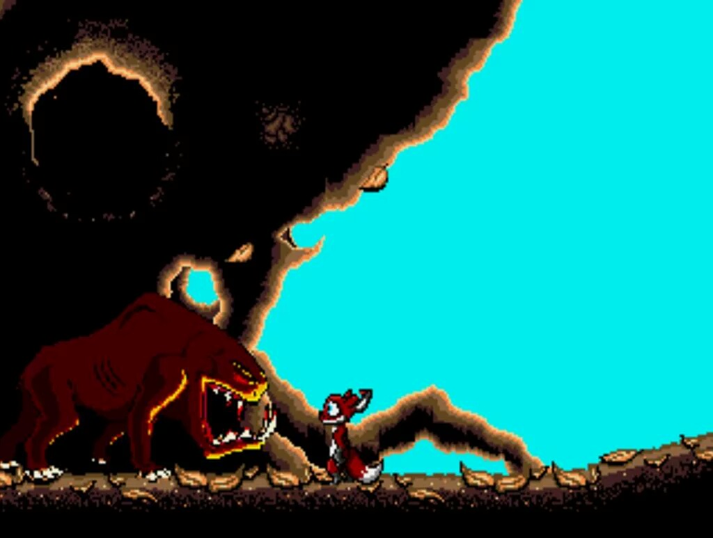
 The small teaser video from last week showed Nymn walking through the world for a small glimpse of the environment, but the gameplay itself will be faster paced; Nymn is a quick and nimble creature who can walk on two legs, and scurry along quickly on all four. The platforming experience of Tanglewood is one that I’ve spent a lot of time perfecting – it’s important to me that Nymn’s controls and physical behaviours are accessible and familiar to fans of both legacy Mega Drive titles and the modern platforming games by which Tanglewood was inspired. Since my
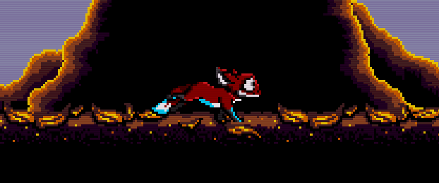


You must be logged in to post a comment.